
Explore a breadboard
Content and en/rw/fr translations are drafts pending fluent educator review.
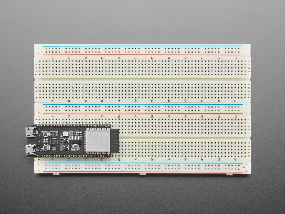
Reference photograph; identification only, not a wiring or pin map. See sources for image provenance.
Learning objectives
- Identify connected holes, rails and the center gap.
Before this introduction
Start here — no prerequisite
A solderless breadboard holds components for reusable experiments. Inside, metal clips connect groups of holes. On the common model labelled a–j, a1 through e1 share one connection; f1 through j1 share another. a1 and a2 are separate. The center gap separates e1 from f1. Numbers identify rows, not connections across the gap.
Side rails distribute power and ground only after you connect them to a supply. A + stripe does not create power. Opposite rails are not automatically connected. Some boards split a rail halfway; others do not. Check the exact board diagram or continuity with power disconnected. Never assume a stripe proves continuity.
Learn only: circuit building, board simulation, firmware export and physical connection for this board are not available here.