
Power, signals and an LED return path
Content and en/rw/fr translations are drafts pending fluent educator review.
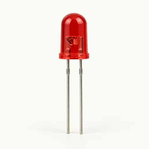
Reference photograph; identification only, not a wiring or pin map. See sources for image provenance.
Learning objectives
- Trace a closed path and distinguish GPIO, supply and GND.
Before this introduction
A supply pin provides a specified voltage; GND is the common reference and return. GPIO means general-purpose input/output: a controlled signal, not a substitute for a power supply. Voltage limits and current limits depend on the exact board. Do not connect a 5 V signal to a 3.3 V-only input.
For an active-high LED teaching circuit, trace GPIO → series resistor → LED anode (+) → cathode (−) → GND. Without the return, the path is open. The resistor limits current and can be on either side of the LED in series. Choose its value for the supply, LED forward voltage and allowed current; never wire an LED directly across a supply. A new through-hole LED often has a longer anode lead and a flat cathode edge; trimmed leads require its datasheet.
Learn only: circuit building, board simulation, firmware export and physical connection for this board are not available here.