
Digital, analog and PWM
Content and en/rw/fr translations are drafts pending fluent educator review.
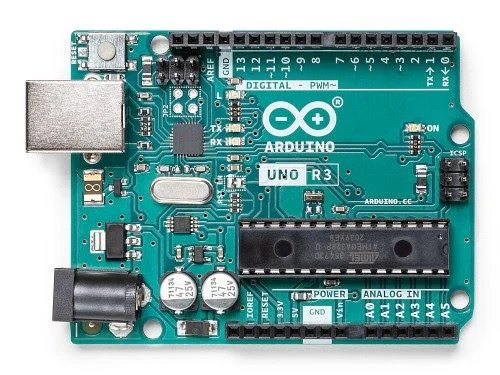
Reference photograph; identification only, not a wiring or pin map. See sources for image provenance.
Learning objectives
- Distinguish two-state signals, measured values and pulse duty cycle.
Before this introduction
Digital inputs interpret LOW or HIGH using voltage thresholds. An analog-to-digital converter (ADC) samples a voltage into a number within a board-specific range. PWM switches a digital output repeatedly; duty cycle is the fraction of each period spent HIGH. 50% duty means half the time HIGH, not a constant half-voltage output. PWM can control perceived LED brightness.
The current light, temperature and water-level percentage sliders are abstract teaching inputs. They do not represent a specific sensor, voltage, ADC calibration or physical driver. A pictured board does not add a component model.
A microcontroller runs firmware to control a focused task. A Linux-capable single-board computer can boot an operating system and run applications. A classroom indicator and a classroom computer have different needs; choose by task, exact voltage and pin capabilities, not brand alone.
Learn only: circuit building, board simulation, firmware export and physical connection for this board are not available here.